Control
DCC – A
Brief Overview
When I first came back to Model Railways one of the biggest innovations
I had missed was the introduction of Digital Command Control, or DCC. When
I had my layouts as a child it was all DC control or nothing – one
big transformer with a plastic knob that you turned to apply power to the
track. And therein lies the problem: ALL trains on the track will move at
once unless they are suitably isolated by having dead sections controlled
by points or switched-breaks in the track. This isn’t too difficult
on a small layout, but as it gets bigger and more complex so the wiring needed
increases exponentially. Add in the complexities of splitting the layout
into sections so that two or more controllers can control multiple trains
and the wiring starts to look like your local telephone exchange!
DCC applies power to the track all the time, but trains will only move when the Command Station tells the small chip (or decoder) fitted inside the loco to do so. This means that you can just select a train and drive it anywhere on the layout without worrying about others moving unintentionally or whether your controller is switched to that particular section of track. The beginnings of this system were around back when I was a teenager with the Hornby Zero 1 system, but microchips not being as ‘micro’ as they are now meant they were WAY too big to fit inside an N gauge loco. From a wiring point of view DCC is an absolute dream – two wires from the controller to the track, that’s it! In reality it’s better to have two wires to every piece of track for ultimate reliable running so you are no longer reliant on track-joiners to conduct the power, but then this applies to DC-wired layouts as well. The only drawback to DCC is the cost: small systems can be had for under £100, a mid-range system between £200-£300, and after that the sky’s the limit! The added cost no matter what system you choose is that each loco or unit needs a decoder, some need more than one for directional lights to operate. These can cost anywhere between £10 and £40 each dependent on quality and available functions, although the cheapest offerings are best avoided. Of course having a controllable chip inside the loco opens up all sorts of possibilities – switchable lights, realistic sounds, smoke generators in steam engines – the only limitations are available space inside the loco and your wallet!
My DCC System
There are many decisions to be made before buying a DCC system; how many
trains you envisage controlling, how many functions (lights, sounds, etc)
you might need, wireless or wired handset, possibility for computer-control,
even down to having buttons or an old-style knob to control speed. So on
good advice I paid a pre-arranged visit to Digitrains just
outside Lincoln where they will happily let you try out various systems
on their test track.
I have to say I was mightily impressed with the service I got, not the
sort of service that steers you towards the most expensive (read profitable)
system, but the sort that ends up with you paying only what you need to
for the system you want based on your personal needs. My preference
was for the Gaugemaster/MRC
Prodigy Advance² shown below.
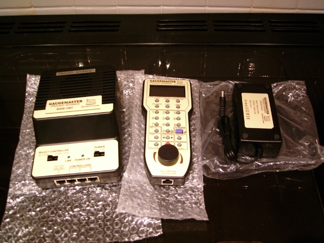
The system consists of a Base Station, Power Supply, and a Walkaround Controller on a lead approx 6’ long. It has more than enough functions if I choose to install sound-chips, and the controller itself has a nice ergonomic design with rotational speed-control and an exceptionally clear LCD display. This last point was the deciding factor against the similar NCE Powercab/PowerPro which only has a two line green backlit LCD display that I found not so easy to read at-a-glance. There are also options available for wireless handset operation or controlling the layout by computer should I so wish later on.
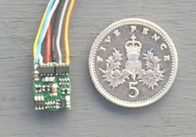
There is a plethora of decoders available out there, all with their pros and cons, and certainly far too many to go into here. The bottom line is you get what you pay for – go for the cheapest and expect problems. My personal choice are the TCS range which offer good value for money, come in a selection of sizes and function-capabilities, and come with a no quibble ‘goof-proof’ warranty where they will replace it free of charge if it fails even if it’s your fault - very useful if you’re doing your own conversions to older non-DCC ready stock not fitted with a socket! The only exception was the use of a CT Electronik DCX74z (shown below) in the Class 04 shunter as this was the smallest decoder available at the time of writing.
Point Control
With DCC you can also operate point-motors by using accessory decoders, however
to keep things simple and because I prefer to do so all points will be
controlled the old fashioned way with switches on what is called a ‘mimic
board’. This is similar to what you would see in any signal box or
control centre these days, where a diagram of the track layout is used
to set routes for trains. On a model railway this mimic board also contains
the switches to change points and in some cases a positive indication of
which way the point is set.
I have incorporated the mimic board into a complete control box which also has spaces for the DCC system to sit, and a DC controller as well to provide power for the point motors and layout lights and accessories. The control box connects to the layout using leads made up from computer ribbon-cable and IDC connectors (both from Rapid Electronics, as are most of my LEDs, etc) plus a couple of home-made power leads.
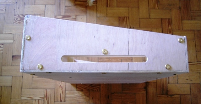
Here's the basic box built from ply and 20mm square pine . . .
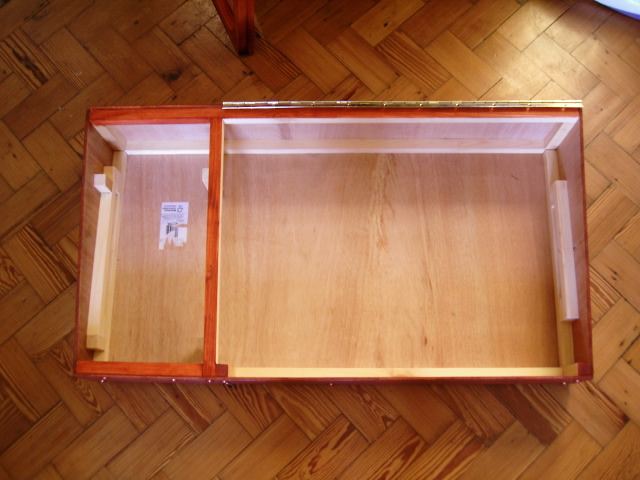
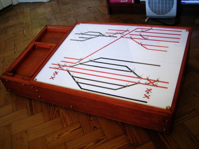
. . . and here it is with the removable tray that holds the DCC base unit and DC controller for points/accessory power
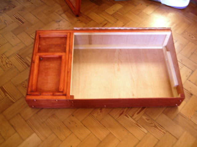
The ends have slots cut where the recessed plugs/sockets will go. This will protect them from damage.
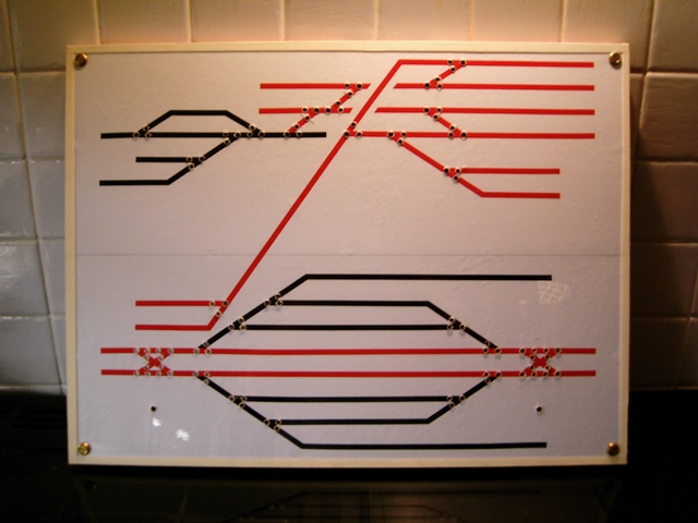
This is the lid that forms the mimic panel. It is constructed from a sheet of 3mm MDF covered with white self-adhesive vinyl (stickyback plastic for all you Blue Peter fans). The red and black lines are 6mm car pinstriping and the whole thing is covered with 2mm acrylic sheet for protection. The holes are for switches and LEDs.
Here it is fitted to the box with switches in place. The lid is hinged at the back for easy access to the wiring underneath.
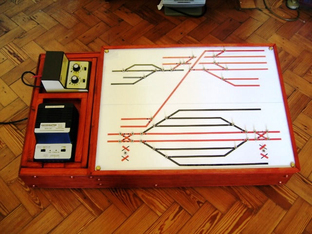
And finally for now, this shows how the removable tray holds both controllers tidily.
Now I just needed to attach a couple of hundred wires to it!!!
I methodically wired each point motor back to the board-edge connectors, then to the control panel and up to the switch. With three wires for each motor going all the way back to the panel (two for throwing the point motor plus one for route indication) this is a slow process to solder all joints properly and keep the wiring tidy.
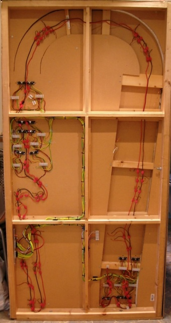
All the point-motor wiring is now finished, so here are some pictures to prove it!
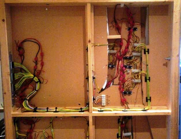
The underside of the whole South Board - red/black are the DCC bus wires.
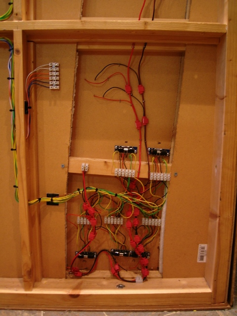
This is the main station junction in the bottom left corner of the above pic. The choc-block with blue/orange/white wires attached provides DC feeds for lights and accessories.
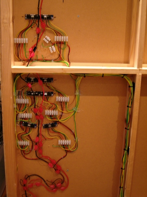
Here is the fiddle yard junction where two tracks become six, with a scissors crossing spanning the bracing to enable any storage road access to/from the two main lines.
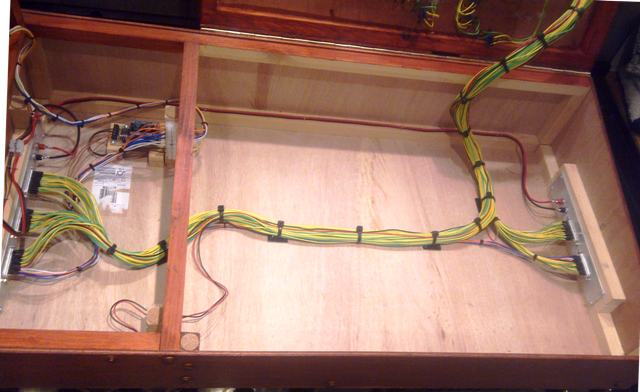
Now the underside of the North Board.
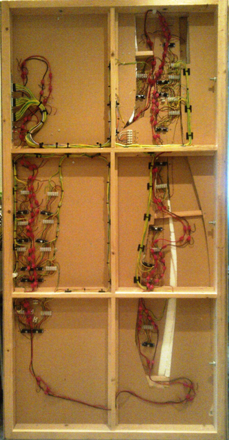
Closer view of the top showing connector-plate (left) and mainline junction (right)
And this is what the control panel looks like fully-wired. Underside of the lid . . .
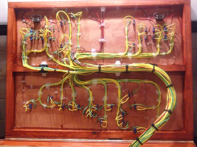
(the green wires to each switch have yet to be LED-fitted for route-indication at a later date)
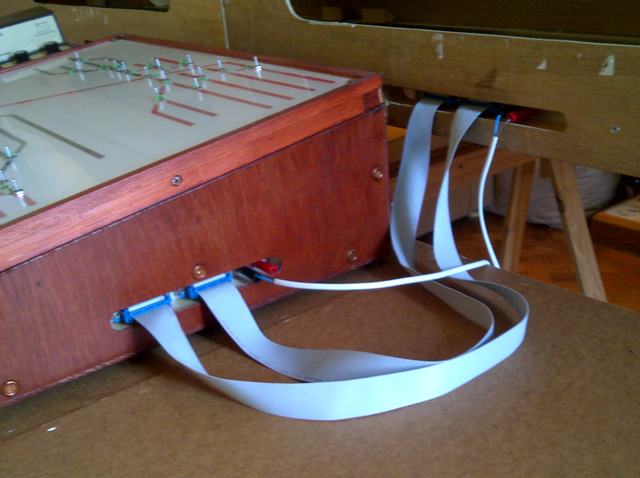
. . . and the inside with connectors at either end.
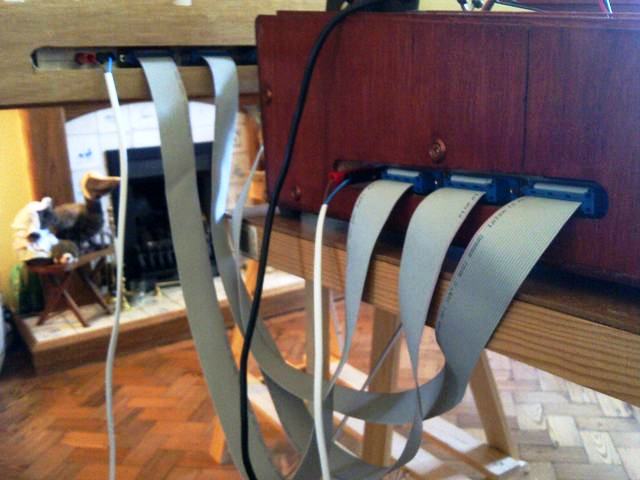
Connection cables are home-made: 25-way ribbon cable with IDC connectors for all the point motor wiring, and twin-core cable with Audio 'banana' plugs for the DCC track power
This is the right-hand end for the South (station) board . . .
. . . and the left-hand end for the North (dairy) board
© Sprintex-net 2023 - Go to Sprintexnet home